Scientific American Supplement, No. 365, December 30, 1882 by Various, is part of the HackerNoon Books Series. You can jump to any chapter in this book here. APPARATUS FOR MEASURING ELECTRICITY AT THE UPPER SCHOOL OF TELEGRAPHY.
APPARATUS FOR MEASURING ELECTRICITY AT THE UPPER SCHOOL OF TELEGRAPHY.
Electro Tuning Forks and their Uses.—On a former occasion I described an instrument to which, in 1873, I gave the name Electro-Tuning Fork, and which is nothing else than a tuning fork whose motion is kept up electrically in such a way as to last indefinitely, provided that the elements of the pile are renewed gradually, and that from time to time the metallic contact is changed, which causes, at every oscillation, the current to pass from the pile into the magnet, which keeps up the vibration.
We reproduce herewith, in Fig. 1, a cut showing in projection one of the simplest forms of the apparatus.
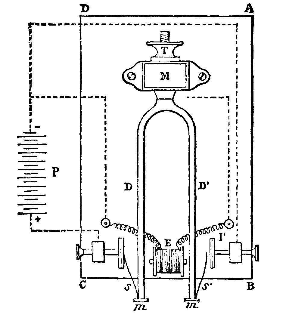
If we imagine the platinum or steel style, s, of the figure to be done away with, as well as the platinized plate, I, and its communication with the negative pole of the pile, P, we shall have the ordinary instrument kept in operation electrically by the aid of the electro-magnet, E, the style, s, the interrupting plate, I, and the pile.
If we preserve the parts above mentioned, the instrument will possess the property of having vibrations of a constant amplitude if sufficient energy be kept up in the pile. In fact, when the amplitude is sufficiently great to cause the style, s, to touch the plate, I, it will be seen that at such a moment the current no longer passes through the electromagnet, and the vibration is no longer maintained. The amplitude cannot exceed an extent which shall permit the style, s, to touch I.
Under such conditions, the duration of the vibrations remains exactly constant, as does also the vibratory intensity of the entire instrument. The measurement of time, then, by an instrument of this kind is, indeed, as perfect as it could well be.
This complication in the arrangement of the apparatus has no importance as regards those tuning forks the number of whose vibrations exceeds a hundred per second, for in such a case these are given an amplitude of a few millimeters only; but it would be of importance with regard to instruments whose number of vibrations is very small, and to which it might be desirable to give great amplitude; for then, as I have long ago shown, the duration of the oscillation would depend a little on the amplitude, but a very little, it is true.
I shall not refer now to the applications of these instruments in chronography, but will rather point out first the applications in which they are destined to produce an effective power.
For this purpose it is necessary to make them pretty massive. The number of the vibrations depends upon such massiveness, and it is necessity to know the relation which exists between these two quantities in order to be able to construct an instrument under determinate conditions. I made in former years such a research with regard to tuning forks of prismatic form, that is to say, of a constant rectangular section continuing even into the bent portion where the parallel branches are united by a semicylinder, at the middle of which is the wrought iron rod as well as the branches. The thickness of the instrument is the dimension parallel to the vibrations; its width is the dimension which is perpendicular to them, and its length is reckoned from the extremity of the branches up to the middle of the curved portion.
It is found that the number of vibrations is independent of the width, proportional to the thickness, and very nearly inverse ratio of the square of the length, provided the latter exceeds ten centimeters.
If we represent the length by l, the thickness by e, and the number of vibrations by n, we shall have the following formula:
n = k × (e / l2)
in which k is a constant quantity whose value depends upon the nature of the metal of which the tuning fork is made.
This constant varies very little from steel to malleable cast iron, and it may be taken as equal to 818270.
Thus, then, we have a means of constructing a tuning fork in which two of the three quantities, n, e, l, are given in advance. Experience proves that no errors are committed exceeding one or two per cent.
It is seen from this that there is a means of increasing the mass of the instrument without changing anything in the thickness, the length or, consequently, the number of vibrations, and this is by increasing the breadth.
It is in this way that I have succeeded in having long massive tuning forks made of malleable iron, giving no more than 12 to 15 vibrations per second, and vibrating with perfect regularity. Fig. 2, annexed, shows one of these instruments of about 55 centimeters length, whose breadth, E, is from 5 to 6 centimeters, and which makes about fifteen double vibrations per second only.
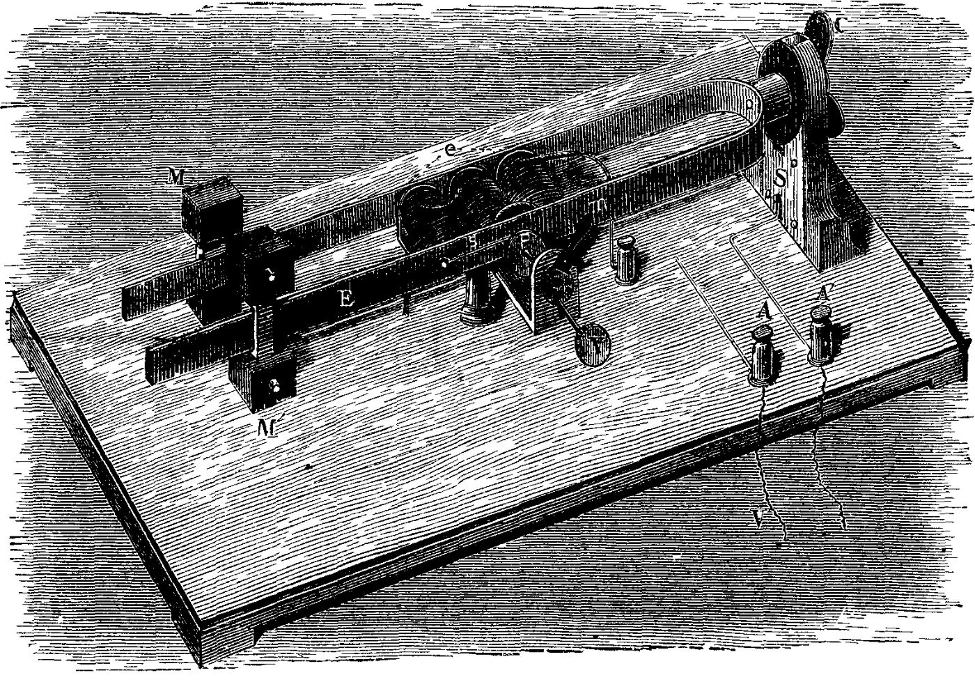
This number might be still further reduced, but at the expense of our being led to exaggerate the longitudinal dimensions of the apparatus in such a way as to make it inconvenient. The object may be attained more simply by loading the branches with slides supporting leaden weights, M, of 500 grammes each. By fixing these slides at different points on the branches, the number of vibrations can be made to vary from simple to double, and even triple. Thus, by fixing them at the extremity of the branches the number of the vibrations is reduced to 5 or 6.
There will be seen in the figure the electro-magnet which keeps up the vibration. This is formed of three simple electro-magnets, whose bobbins have a resistance of no more than 10 ohms, and which are united in series. The interrupting plate, P, against which the style, s, rests at each vibration, is capable of a forward movement, or one of recoil, by the aid of a screw, V, and of an eccentric movement which is produced by a small handle, m, and during which its plane remains invariable. This arrangement permits the point of contact of the style and plate to be varied without changing the precision with which the contact takes place, and all the points of the plate to be slowly used in succession before replacing it. The motion is produced by means of a relatively weak pile, whose poles are connected to the terminals, A and A'. Three Callaud elements of triple surface, renewed one after the other every month at the most, are sufficient to keep up the vibrations continuously, day and night, without interruption, and that too even when the instrument is employed in producing a small mechanical power, as we shall see further on.
We have now seen how electro-tuning forks may be constructed of large dimensions, of large mass, and giving a small number of vibrations per second.
Such instruments are well fitted to perform the role of electrical interrupters, and it was in such a character that one of them figured in the Exhibition of the Upper School of Telegraphy as a type of an interrupter for testing piles.
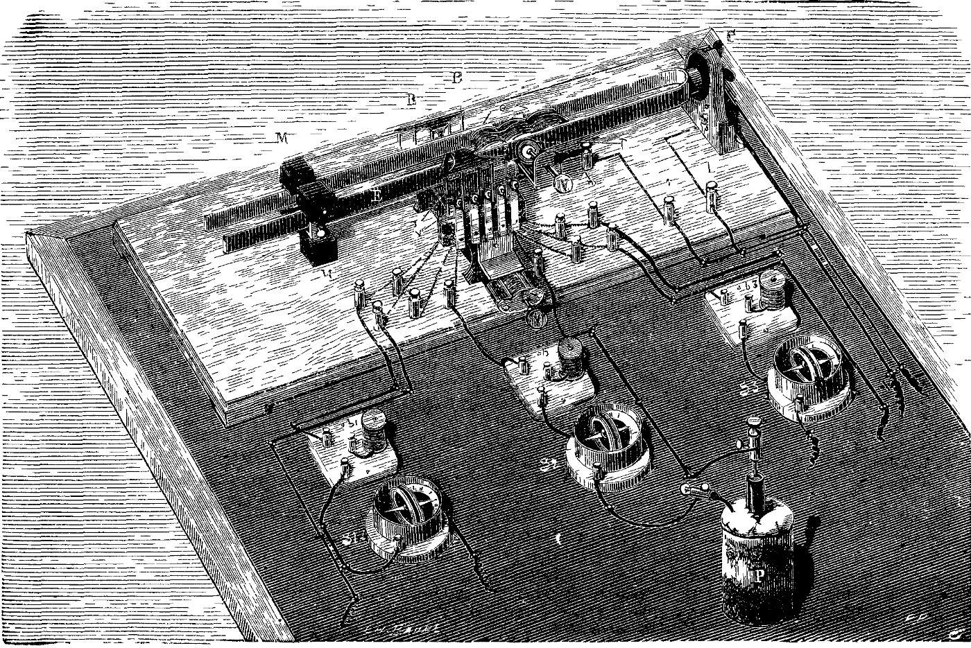
When it is desired to test a pile to ascertain the practicability of employing it in telegraphy, it is necessary to make it perform a work which shall be as nearly as possible identical with that which it will be called on to do, until it is used up, to estimate the duration of such work, to measure regularly the constants of the pile, the electro-motive power, and the internal resistance. Usually, in telegraphy, this work consists in sending over a line of a certain resistance intermittent currents, through the intermedium of suitable manipulators. It suffices then to cause the branches of the electro tuning fork to play the role of one of these manipulators. For doing this the tuning fork carries two insulating ebonite or ivory strips, B B (Fig. 3), which, at every oscillation, abut against vertical brass springs, r. Each of these latter is located in front of the platinized point of a screw, v, which is affixed to a small metallic tongue. The springs and tongues are insulated from each other, and are mounted on a piece which may be moved by a screw, V, so as to cause the springs of the strips, B B', to approach or recede according to the amplitude of the instrument's vibrations. Each spring and tongue is connected with terminals affixed to the base of the apparatus. One of the poles of one element, P, of the pile is connected with the tongue and corresponding screw, while the other pole is connected with the screw in front of it through the intermedium of a galvanometer, g2, which gives the intensity of the intermittent current, and of a resistance coil, b2, which performs the role of an artificial telegraph line. The apparatus being set in operation, it will be seen that the current from the pile is emitted once at every vibration.
Thus there may be exhausted as many pile elements as there are springs, and that, too, simultaneously; and the contacts of the screws and springs can be regulated in such a way that the duration of the emissions shall be the same for all.
At the laboratory of the School of Telegraphy one of these instruments has operated without interruption, day and night, during eighteen months.
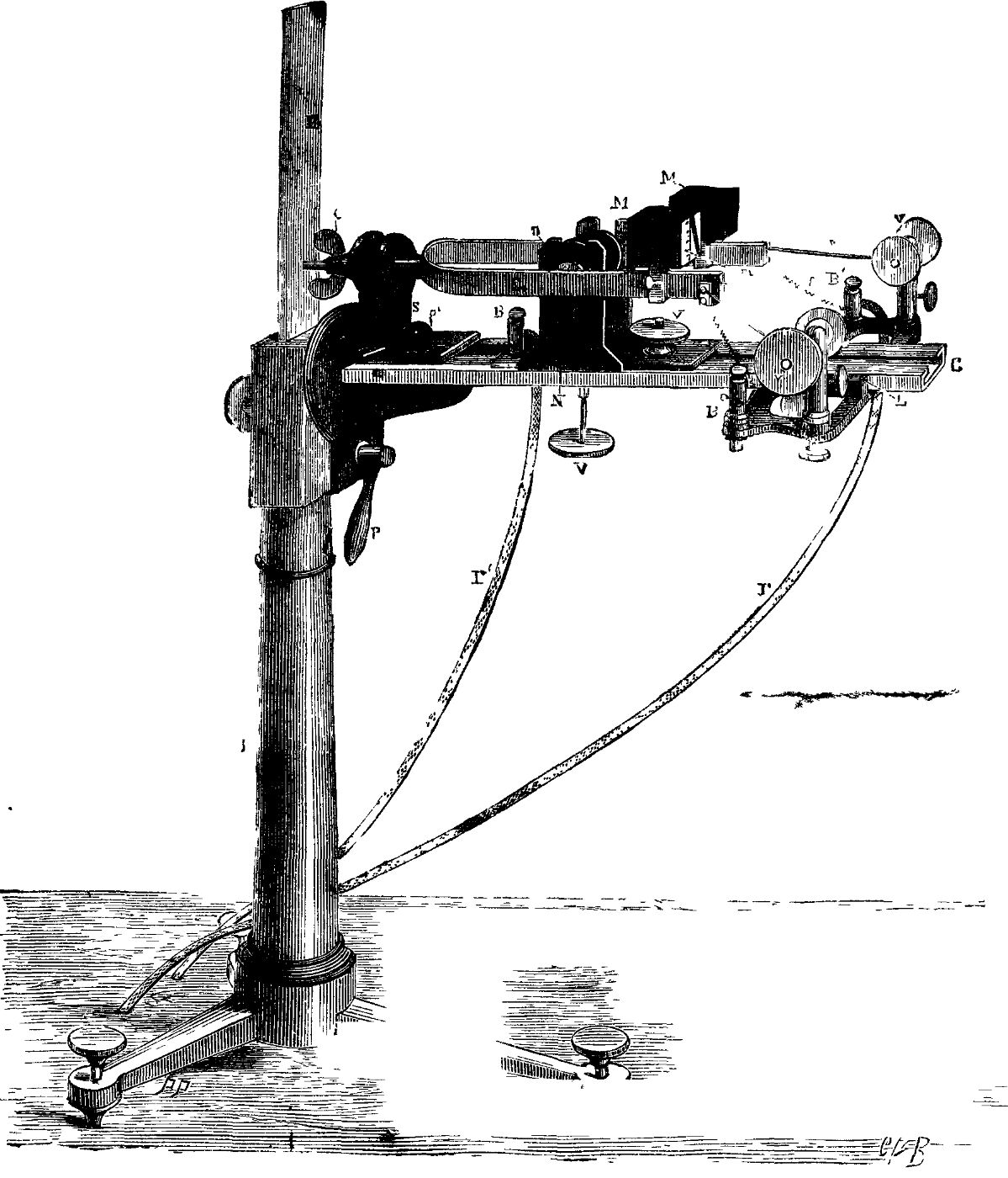
The apparatus shown in Fig. 4 is also an interrupting electro-tuning fork, but it makes a much greater number of vibrations than the preceding, and may serve for other electric tests.
The operation of the tuning fork is kept up electrically by the aid of the screw, v, and the corresponding plate; of the style, s, and of the fine wire spiral spring, f, both insulated from the fork, from the electro-magnet, N, and from the two wires, F F', which communicate with a pile.
The interrupting system is symmetrical with the first. It consists of the style, s, of the spiral spring, f, of the screw, v, and of the plate that this carries at its extremity. The terminal, B, which carries the spring, f, and the rod which carries the screw being insulated from each other, it is only necessary to cause to terminate therein the extremities of a circuit comprising one pile, in order to produce in the circuit a number of interruptions equal to that of the tuning fork's vibrations. Provided the lengths of the springs, f and f', are proper, such vibrations will not be altered.
Moreover, the instrument is so arranged as to produce vibrations whose duration can be varied at pleasure and kept constant during the whole time the experiments last. This is done by modifying the amplitude of the vibrations; for the greater the amplitude, the longer likewise the duration of the contact of the style, s, on the corresponding plate, and the shorter the duration of the interruption. In order to modify the amplitude, the action of the electro-magnet on the branches of the apparatus is made to vary. To effect this, the electro-magnet is made movable perpendicularly by the aid of a screw, V, between two slides, so that the core, N, may be moved with respect to the median line of the branches, and even be raised above them. Its action diminishes, necessarily, while it is being raised, and the amplitude of the vibrations likewise diminishes gradually and continuously. It may thus be made, without difficulty, to vary from two to three tenths of a millimeter to three or four millimeters or more.
But it is not sufficient to cause the amplitude to vary; it is necessary to measure it and to keep it constant at the value desired.
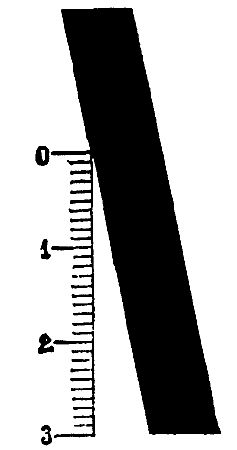
The measurement is effected by the aid of a very simple apparatus that I have before described under the name of the vibrating micrometer. This is a small square of paper carrving a design like that shown in Fig. 5, and which is seen in Fig. 4 glued to one of the masses, M, which serve to vary the number of the instrument's vibrations. This figure is in fact, an angle, one of whose sides is graduated into millimeters, for example, and the other forms the edge of a wide black band. The apex of the angle is above and the divided side is perpendicular to the direction of the vibrations.
Under such conditions, when the fork is vibrating, the apex of the angle, by virtue of the persistence of impressions upon the retina, seems to advance along the graduation in measure as the amplitude of the vibrations increases. If an angle has been drawn such that the slope of one of its sides to the other is one-tenth, it is easy to see that for each millimeter passed over apparently by the apex of the angle, the amplitude will increase by two-tenths of a millimeter.
This is the way, then, that the amplitude is measured. On another hand, it suffices to keep the apex of the angle of the micrometer immovable, in order to be sure of the constancy of the tuning fork's amplitude; and this is done, when necessary, by causing the screw, V, to move slightly.
The instrument represented in Fig. 4 is, moreover, fixed to a support devised by Mr. A. Duboscq, so as to make it possible to give the tuning fork every position possible with respect to a vertical plane; to raise it or lower it, and to move it backward or forward so that it may be employed for chimography, and in all those experiments in which electro-tuning folks are used.
E. MERCADIER.
About HackerNoon Book Series: We bring you the most important technical, scientific, and insightful public domain books.
This book is part of the public domain. Various (2006). Scientific American Supplement, No. 365, December 30, 1882. Urbana, Illinois: Project Gutenberg. Retrieved https://www.gutenberg.org/cache/epub/18763/pg18763-images.html
This eBook is for the use of anyone anywhere at no cost and with almost no restrictions whatsoever. You may copy it, give it away or re-use it under the terms of the Project Gutenberg License included with this eBook or online at www.gutenberg.org, located at https://www.gutenberg.org/policy/license.html.
