Scientific American, Vol. XXXVII.—No. 2. [New Series.], July 14, 1877 by Various, is part of the HackerNoon Books Series. You can jump to any chapter in this book here. COLLENDER'S IMPROVED BILLIARD TABLE.
COLLENDER'S IMPROVED BILLIARD TABLE.
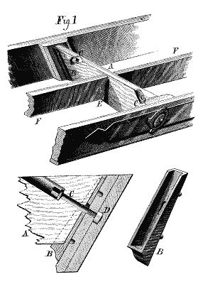
In the accompanying engravings, we illustrate two important improvements in the construction of billiard tables, which have recently been devised by Mr. H. W. Collender, the well known billiard table manufacturer of this city. The first, which is represented in Fig. 1, relates to the construction of the bed-supporting frame, and aims to render the same stronger while cheapening its manufacture. In putting together the body and framework of the table, the usual practice is to cut away the stock of the cross beam and longitudinal beam, and halve them together. Longitudinal grooves are also formed on the inner surface of the side and "broad rails," to accommodate tenons on the ends of the cross beams; and the latter are secured in place by bolts fastening their ends to the broad rails. Mr. Collender claims that, by this mode of construction, not only are the cross beams weakened by being halved together, but the broad rails are also weakened by the cutting away of this stock near the middle to effect the framing into them of the ends of the cross beams.

From Fig. 1, it will be seen that the cross beam, A, is combined with the side broad rails in the following manner: Upon the inner face of each broad rail is secured a cast iron socket piece, B, into which fits one end of the cross beam, A. From said beam the bolt, C, passes through the shoe, B, and is secured by a nut, D, let into the stock of the broad rail. The shoe, B, has lugs which enter the broad rail; and the aperture in it, through which the bolt passes, is made oblong to admit of the drawing of the parts together after the insertion of the bolt. Upon the sides of the cross beam near the middle, and directly opposite each other, are two shoes, E; these have no bolt holes. In them are placed the adjacent ends of the longitudinal beams, F, the other extremities of which are seated in shoes on the broad rails. The shoes, E, have their lugs of such a length, compared with the thickness of cross beam, A, that when put in place on said beam said lugs will come together. The advantage of this is that, should the beam, A, shrink in width, the shoes on each side of it will still maintain their proper relation to form immovable abutments for the ends of pieces, F. This construction allows of shorter stuff being used in the manufacture, and renders the framework stronger.

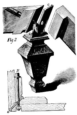
n Fig. 2 is illustrated a new method of forming the corners of the table. Hitherto it has been customary to use corner blocks, of various sizes according to the dimensions of the table, located one at each corner. Into these the broad rails were framed and secured. To this arrangement Mr. Collender adduces a long category of objections, based on the possibility of the weight of the bed being thrown on these blocks in case of shrinkage of the frame, on the fact that the corner of the table bed must necessarily be left without any support where it extends over the upper end of the corner block, and also that in a bevel table, in which the area of the top of the corner block is unavoidably much greater than that of the top of the corner block of a vertical-sided table, a large portion of the table bed will be left without any support.
The new device consists of a cast iron union plate, G, which is bolted to the leg as shown. The broad rails and casting are securely fastened by the bolt, H. It will be seen that this bolt, passing through the end of one broad rail, and into a nut let into the other rail, will securely draw and hold together the ends of said rails and the interposed metal plate clamped between them, and that as the plain ends of the wooden rails just fit (widthwise) between the projecting heads on the edges of said interposed plate, the latter will form a sort of housing for the ends of the rails. And it will be understood that in this construction not only does the bead on the outer edge of the plate overlap the edges of the rails and form a neat and durable corner finish to the body, but the broad rails being bolted together in the direction of the grain of the wood with only an interposed metal plate, there will be no tendency to a loosening of the union of the parts of the frame. The main importance of this invention rests in the idea of dispensing with the usual corner blocks, and thus permitting the top edges of the broad rails, on which the bed rests, to practically come together and afford a perfect support to the bed clear out to the corners of the latter; at the same time the whole structure is rendered stronger and more durable with less weight of material.
These inventions are the subject of separate patents, that of the first being dated April 4, 1876, and of the second, November 16, 1875. For further information, address the manufacturer and patentee, Mr. H. W. Collender, 738 Broadway, New York city.
About HackerNoon Book Series: We bring you the most important technical, scientific, and insightful public domain books.
This book is part of the public domain. Various (2012). Scientific American, Vol. XXXVII. —No. 2. [New Series.], July 14, 1877. Urbana, Illinois: Project Gutenberg. Retrieved https://www.gutenberg.org/cache/epub/38481/pg38481-images.html
This eBook is for the use of anyone anywhere at no cost and with almost no restrictions whatsoever. You may copy it, give it away or re-use it under the terms of the Project Gutenberg License included with this eBook or online at www.gutenberg.org, located at https://www.gutenberg.org/policy/license.html.

