Scientific American, Volume XXIV., No. 12, March 18, 1871 by Various, is part of the HackerNoon Books Series. You can jump to any chapter in this book here. Improved Compound Spiral Car Spring for Railway Carriages.
Improved Compound Spiral Car Spring for Railway Carriages.
Our engravings illustrate an improved compound car-spring, which appears to possess all the requisites of a first-class spring, combining in its construction extreme simplicity with great strength, and a feature whereby the power of the spring increases with increase of the load, and vice versâ, so that its flexibility remains nearly constant for all loads.
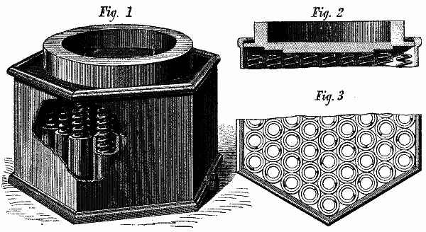
Fig. 1 is a perspective view of this spring, with a portion of the side of the case broken out to show the interior arrangement of the spiral springs. Fig. 2 is a section of the compressing plate. Fig. 3 is a plan view, showing the arrangement of the tubes which enclose the springs.
The case is cast in two pieces. Its vertical wall is cast in a single piece, and has at the top a flange or bead extending inwardly, against which the compressing plate abuts when the spring is not compressed, as shown in Fig. 2. A bottom plate completes the case.
The spiral components of the spring are inclosed in tubes, as shown in Figs. 1 and 3. It is not deemed essential that these tubes should be seamless, or that their edges, brought together in bending, should be soldered, brazed, or welded. They act merely as guides to compel the component springs to expand or contract in vertical lines, and need only be strong enough for that purpose.
The compressing plate is formed with concentric steps or ledges, as shown in Fig. 2, so that with light loads, only a portion of the component spirals act. With a heavier load a new series of spirals is brought into action, and so on, till the spring is loaded to its full capacity. This feature is novel, and as important as novel, as it gives the spring a far more easy and flexible carriage, with light loads, than would be the case if all the spirals were permitted to act.
In putting the spring together, the vertical part of the case is inverted. The compressing plate is then placed within the case, resting upon the inner flange of the case above described. The tubes with their inclosed springs are then arranged in position, as shown in the plan view, Fig. 3. The bottom plate of the case is then placed in position, and held to its place by lugs and rivets, as shown in Fig. 1; the spring is then ready for use.
The employment of tubes in the manner described, enables springs of the greatest practical length to be used, without the sectional or division plates met with in other spiral car springs. A greater and easier movement is therefore obtained. These springs can, it is claimed, compete in price with any spring in market, and are guaranteed by the manufacturers. Patented through the Scientific American Patent Agency, December 27, 1870, by Albert Potts, whom address for further information, No. 490 North Third street, Philadelphia, Pa.
About HackerNoon Book Series: We bring you the most important technical, scientific, and insightful public domain books.
This book is part of the public domain. Various (2006). Scientific American, Volume XXIV., No. 12, March 18, 1871. Urbana, Illinois: Project Gutenberg. Retrieved https://www.gutenberg.org/cache/epub/19180/pg19180-images.html
This eBook is for the use of anyone anywhere at no cost and with almost no restrictions whatsoever. You may copy it, give it away or re-use it under the terms of the Project Gutenberg License included with this eBook or online at www.gutenberg.org, located at https://www.gutenberg.org/policy/license.html.


